
Improved Contact Image Sensor (CIS) resolution enables detection of breaks, voids, and holes as small as 0.25-mm in screen-printed antenna traces on automotive glass
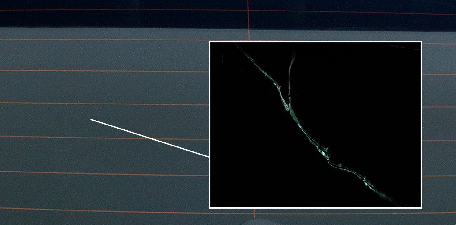
Screen-printing defects arise for many reasons. Especially during the challenging application of silk-screen printing silver ink antennas onto automotive glass. Root cause of defects include insufficient ink flow, air pockets, and stretched or clogged screens, all of which can contribute defects such as trace thinning, partial breaks, voids, holes, or full breaks in the silver-ink trace.
It goes without saying that such antenna-trace defects lead to antennas that will not function as intended. Consequently, steps must be put in place to identify such defects before flawed products are shipped to customers. Equally as important, when a screen-printing process starts producing defective parts it’s likely to continue producing defective parts until the defect is identified and the root cause of the defect is fixed.
Because not catching detects right away can lead to an entire lot of flawed product being produced, identifying defects as soon as they occur is a critical step in reducing waste, costs, rework, and lost production time. When one of largest glass manufacturing companies in North America wanted to identify smaller defects in its screen-printing process, it tapped the expertise of a machine vision systems integration company.
Detecting Screen-printed Antenna Defects On Glass
Formerly, the company’s glass-inspection system couldn’t detect 0.25 mm or smaller breaks, so they might have had an entire day’s worth of production resulting in a whole batch of decreased or non-functional antennas. To solve the problem, the integrator chose to develop a system based on a KD-Series contact image sensor (CIS) from Mitsubishi Electric Corporation.
The Mitsubishi Electric KD Series CIS integrates an array of sensor IC's, a rod lens array, and a light source inside of a compact image sensor module that can be installed closer to the surface of the glass than traditional machine vision cameras. Since the CIS has an all-in-one structure that includes a lens array, light source, and sensor ICs in a single frame, it’s not only more compact, but also easier to install since it eliminates the need to assemble discrete parts such as lenses, light sources, and cameras to build up an imaging system.
Also, the KD Series CIS uses a rod lens arrays that creates images with less distortion than ordinary line scan camera systems, which improves accuracy. Finally, the CIS can capture images with higher resolution than lenses used in common machine vision line scan cameras so it enables smaller defects to be more easily detected.
Maintaining Focus
In order to scan the full surface of automobile windows, the KD Series KD6R926MX with 926 mm (36 in.) scan width was used. The system also needed to accommodate various glass thicknesses and the CIS must maintain a 12 mm working distance from the glass surface to achieve the highest image quality possible. To maintain focus regardless of glass thickness, the inspection system uses two compact linear actuators that move the CIS camera vertically up to 25 mm (1 in.) for optimal focus.
Before the inspection begins, an operator first places a well-printed part on the conveyor, then selects the “Acquire Golden Image” prompt on the human-machine interface’s (HMI) grid-based menu system, which defines the inspection criteria. Then the operator selects the model of glass that will be inspected, and the motors adjust the height of the CIS camera.
During operation, two robots pick up stacked glass from two separate pallets, and place each onto a conveyor. As each piece of glass moves along the conveyor, a photo eye detects its presence and triggers KD Series CIS image acquisition to start building up the image line by line. A programmable, incremental encoder tracks the motion of the glass as it moves through the CIS camera’s field of view, providing feedback for dynamic image formation adjustments that maintain a square pixel shape to minimize compression and stretching artifacts within the image.
High-speed Camera Link® Interface
As each piece of glass travels under the CIS camera, 600 dpi images are captured. With a 21,888-pixel line scan image sensor, the CIS camera achieves a scan speed of up to 43 kHz and features a 929.6 mm scan width, Camera Link® interface, a white LED array, and a design offering 12-mm aligned CIS sensor chips. Acquired images are transferred through a Camera Link® frame grabber in a PC. Then proprietary software performs image analysis to detect defects.
To speed up pattern search operation, the CPU first scales down each image, which is approximately 250 MPixels in size, to minimize the amount of data being processed. Once the part is located within the image, the “Golden Image” traces are overlayed on the full image allowing each intersection to be extracted from the model, with its own template. Each template can be masked, cropped, and re-centered in a visual image editor.
The system automatically identifies each intersection. Distinct pattern matching algorithms for 90° and Y-shaped intersections inspect and mask each intersection. By masking each intersection, a single algorithm that uses a radial search for right and left trace edges closest to the centerline of the pattern is used to inspect all of the remaining line segments.
Five-Second Total Inspection Time
With a two-second image acquisition time and a three-second inspection time, each piece of glass takes a total of about five seconds to inspect. To achieve this speed, pattern matches run in eight parallel loops on the PC, taking only 5-10 ms to get all eight results. Ultimately, the system detects line breaks down to 3 pixels wide, air pockets down to an area of 3 x 3 pixels, and chips down to 12 pixels wide that cause the trace to narrow, as well as any trace width variation greater than 4 pixels.
The HMI flags the operator with a graphic indicator when a defect is detected and highlights the location of the defect on the display so that the operator can zoom in for a closer look. If a defect is detected and the operator unavailable, a third robot removes the glass using a padded vacuum gripper to prevent damage and places it into an accumulator.
Glass that passes inspection moves advances into the furnace. Pass/fail signal are relayed via I/O to a Mitsubishi Electric programmable logic controller (PLC) that synchronized conveyor and robots operation during the process.
The conveyor surface used in this system a finger like 1 to 2 mm high texture that prevents glass from sticking and enabling the robots to remove defective glass more easily from the conveyor. Another benefit of the CIS camera in this system is that it’s 1-mm depth of field makes it immune to picking up noise in the image from the texture of the conveyor through the glass.
Rather than making pass-fail decisions, the new system allows the manufacturer to score various features in finite amounts on a sliding scale. An air pocket below the threshold can be accommodated if it doesn’t impact quality, but several of them in a small area would cause it to fail.
The KD series CIS includes two models one with built in illumination and one without illumination. The built in illumination models structure includes a lens array a light source and sensor ICs. The non-illumination model provides the flexibility to use external light sources to achieve various light source angles, settings, and transmitted light options. Both options come in various standard sizes to meet he meets of a variety of applications.
For more detailed KD series CIS model information and specifications, download the datasheet.