
Contact image sensor (CIS) reduces time and materials required for digital printhead alignment process
When PCMC (Green Bay, WI, USA; www.pcmc.com), wanted to reduce the cost of printhead alignment on its digital print equipment, it developed a machine vision system to verify proper printhead alignment on its digital printing press. Instead of using common line scan cameras, which have distortion at the ends of the field of view and require sufficient working distance, the vision system relies on KD-Series contact image sensors (CIS) from Mitsubishi Electric Corporation.
PCMC is a leader in tissue converting, packaging, flexographic and digital printing, bag converting and nonwovens technology. The CIS application was designed for its two-stage industrial inkjet print engine, which prints on a web running at speeds greater than 450 feet per minute (fpm). One stage prints the back (verso) of the web. The other prints the front (recto) of the web.
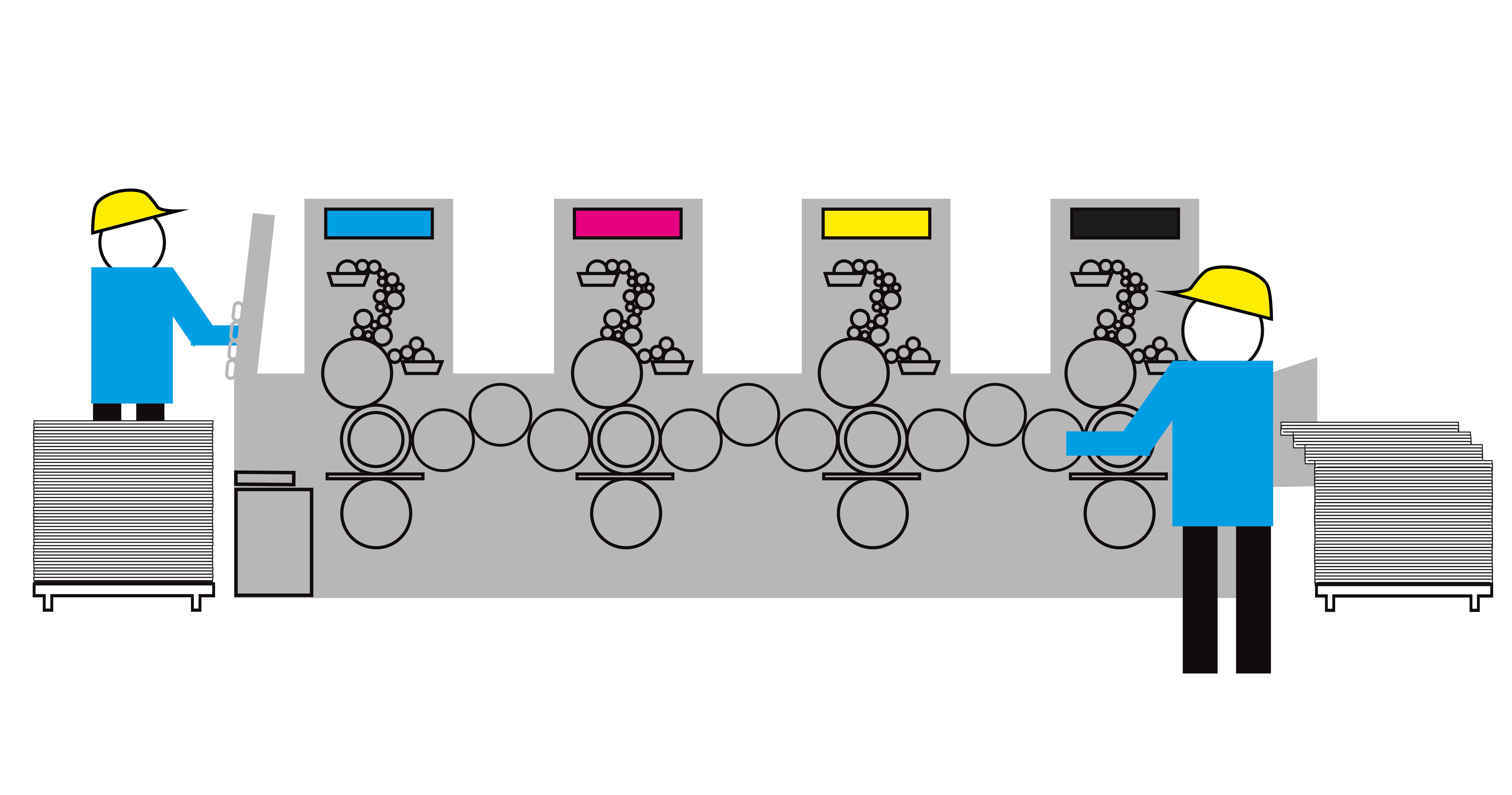
A printbar for each color that is used in the printing process—black, cyan, magenta, and yellow (KCMY)—is required for each stage. Each of the four printbars on each stage requires two printheads in order to cover the entire width of the web, for a total of eight printheads. If the eight printheads on each stage are not properly aligned, with dots in the four-color planes perfectly positioned, accurate reproduction of the full gamut of visible color is not possible because color reproduction will suffer from distortions in the intended color and white outlines or color “halos” may inadvertently appear at the edges of graphic features.
Manual Printhead Alignment
Printhead alignment is required after any mechanical work on the printbars, after replacing printheads, and even after changing substrates. To realign the printheads, the press operator must first cue up the alignment chart to the print engine.
Next, the press operator runs the web at about 150 fpm, printing several copies of the alignment chart. Then, before stopping the web, the operator waits for the printed charts to reach the end of the press. Finally, the operator must collect the printed alignment charts.
To access the printed charts, the web must be cut and the roll partially unwound before the operator can cut out a front-side and a back-side chart, which are then each placed on an 11 × 17 in. flatbed scanner, and scanned to 300 dpi TIFF files. Finally, image analysis is performed on the digital images, deviations are calculated, and corrections are applied by the print engine’s calibration function.
Automated Printhead Alignment
In contrast, the new process replaces the 11 × 17 in. flatbed scanner with a Mitsubishi Electric KD-Series CIS KD6R587CXS, a color/mono switchable with 587mm (23 in.) scan width, and a frame grabber. This approach streamlines the printhead alignment process, providing a faster and less wasteful method for aligning the four color printheads on each stage.
The process again starts with the operator cueing up the alignment chart to the print engine and printing several copies with the web running at a speed of approximately 150 fpm. However, with the new method, the operator does not have to wait for the printed charts to reach the end of the press or collect them, which saves time and eliminates the need to cut and partially unwind the roll.
Instead, the CIS line scan camera and a frame grabber capture the front and back alignment charts as they are printed and write the TIFF files to the print engine’s control PC. Then the calibration function of the print engine analyzes the TIFF files, calculates the deviations, and applies the corrections, reporting either a successful result or a fault.
One CIS For Each Stage
The vision system used a CIS line scan camera installed on each stage of the digital press. One CIS captures alignment chart images on the back, and the other CIS captures alignment chart images on the back. An encoder tracks the motion of the alignment chart on the web as it moves through the CIS field of views, providing feedback through an encoder splitter to the control PC. A CoaXPress frame grabber takes the web encoder input to ensure that the imager is always imaging precisely at 300 dpi, regardless of web’s speed, providing for dynamic image formation adjustments that maintain a square pixel format to minimize compression and stretching artifacts within the acquired image.
The KD Series CIS integrates an array of sensor IC's, a rod lens array, and a light source inside of a compact image sensor module. A short working distance means that it can be installed closer to the surface of the web than traditional machine vision cameras. Its rod lens arrays improves accuracy because of its 1:1 imaging ratio, creating images with less distortion than ordinary line scan camera systems.
Since the KD Series CIS has an all-in-one structure that includes a lens array, light source, and sensor ICs in a single frame, it’s not only more compact, with a lower profile that makes it ideal for this application, but it’s also easier to install since it eliminates the need to assemble discrete parts such as lenses, light sources, and cameras to build up an imaging system.
The KD Series CIS specified for this application features a 587 mm scan width, 600 pixels per inch for a total of 13,824 pixels, and a CoaXPress interface. An integrated, high intensity, homogeneous LED light array ensures optimally aligned illumination with respect to the sensor, making alignment and calibration of external light sources unnecessary.
The KD series CIS includes two models one with built in illumination and one without illumination. The built in illumination models structure includes a lens array a light source and sensor ICs. The non-illumination model provides the flexibility to use external light sources to achieve various light source angles, settings, and transmitted light options. Both options come in various standard sizes to meet he meets of a variety of applications.
For more detailed KD series CIS model information and specifications, download the datasheet.